
Springfield Armory Museum - Collection Record
Send us your own comments about this object.
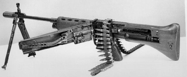
| Title: | GUN, MACHINE - U.S. MACHINE GUN T44 7.92MM |
| Maker/Manufacturer: | BRIDGE TOOL & DIE WORKS |
| Date of Manufacture: | 1946 |
| Eminent Figure: | |
| Catalog Number: | SPAR 909 |
| Measurements: | OL: 98.4CM 38 3/4" BL: 50.1CM 19 3/4" 14 lbs. |
Object Description:
U.S. MACHINE GUN T44 7.92MM
Manufactured by Bridge Tool & Die Works, Philadelphia, Pa. in 1946 - The gun is a conversion of the FG42 German, Light, Magazine Feed Machine Gun, with the belt feeding mechanism of the MG42 German, Belt Feed Machine Gun. The mechanical solution for the conversion was provided by the Bridge Tool & Die Works. The weapon is gas-operated blowback type combination; air-cooled; bipod supported; with forward handgrip and rear shoulder stock.
The receiver body in which the essential parts of the gun operate is a sheet metal fabrication. The barrel is permanently mounted into the forward end, and the receiver swaged circumferentially into a recess around the rear end of the barrel and secured by a locking ring, likewise swaged. The hinge member about which the feed mechanism rotates is welded to that portion of the receiver body directly rearward from the swaged area, thereby making the receiver body, barrel and hinge member an integral unit. Holding the receiver body in a normal firing position, there is an opening on the left-hand side running longitudinally from the welded hinge member for the length of the housing. This opening is bridged in one instance at a point located approximately 4" rearward from the hinge member by the ejector assembly. The resultant opening between the hinge member and the ejector assembly permit the receiver plate to position the shell cartridge for insertion into the barrel. Directly opposite this opening there is a similar small opening through which the cartridge cases are ejected.
The muzzle end of the barrel accommodates the muzzle brake assembly, bipod and front sight. The front sight is held in radial alignment by a milled surface along the top side of the barrel, and locked in place by the muzzle brake mounting ferrule, which at the same time serves as a mounting on an external diameter for the bipod. The muzzle break is threaded onto the muzzle brake mounting ferrule and locked in place by a spring latch attached tot he front sight which registers in a milled slot in the end of the muzzle brake. The function of the muzzle brake is to absorb a percentage of recoil action.
The gas cylinder is tubelike in appearance and mounted beneath the barrel. It is attached on the forward end by a collar, rising up from the forward end of the gas cylinder, which slides on and shoulders against a turned diameter at a point midway the length of the barrel. The rear end of the gas cylinder is turned for a slip fit into a diameter beneath and part of the rear end of the barrel. The gas cylinder is held in place by the gas cylinder locking lug which is threaded onto the barrel. When the gas cylinder is in place a port in the collar end of the cylinder lines up with a similar port in the barrel. This port is for conducting the flow of gas from the barrel into the gas cylinder during the firing cycle. The amount of gas to flow is determined by the radial positioning of the gas cylinder orifice selector which is inserted through the collar portion of the gas cylinder perpendicular to, and in line with, the gas port in the barrel in a manner so as to obstruct the flow of gas from the barrel into the gas cylinder. The gas cylinder orifice selector is screw-like looking in appearance, however, absent of threads. The head is cross slotted, and the body portion has three notches in radial alignment with the cross slots in the head, and the notches increase in size from zero (or no notch) to about 1/16" deep by 3/32" wide. The four quadrants formed by the cross slotting of the head are center punched in depth to correspond with the size of the notch in radial alignment. It is therefore possible to determine, by the position of the center punches, the size orifice between the barrel and gas cylinder, and to increase or decrease accordingly. The gas cylinder orifice selector is retained in position by the gas cylinder orifice selector retainer, which is a 'U' shaped spring, yokelike on one end which fits into a recess near the end of the gas cylinder orifice selector, thereby retainin of the gas cylinder orifice selector, thereby maintaining the radial alignment between the orifice selector and the gas port. The gas cylinder orifice selector retainer serves a dual and reciprocal service with the gas cylinder pressure regulator, fitting itself by spring action into radial slots milled into the perimeter of the gas cylinder pressure regulator. The gas cylinder pressure regulator is threaded into the gas cylinder on the forward end, thereby regulating the head space in the gas cylinder as the milled slots in the perimeter become engaged with the spring action of the gas cylinder orifice selector retainer. By this method the depth of penetration can be controlled with the full seating of its machine surfaces, thereby giving adjustment for regulation, at the same time serving its reciprocal role, that of retaining the gas cylinder orifice selector retainer. The gas cylinder has four radial parts located at sufficient distance from the forward end to permit the piston rod in its rearward action as a result of the expanding gas to unlock the bolt before uncovering these ports, which then permit an air intake into the gas cylinder as the blowback action of the bolt comes into effect.
The piston rod is tubelike in appearance, closed on the forward or piston end. The rear portion has a tongue rising up from the top-side which is yoke shaped at its end to accommodate the firing pin, thereby controlling its forward and rearward movements within the bolt. The rear portion underneath is machined in such a manner that the sear with either lock and hold back, or permit to ride over, depending upon the setting of the sear, thereby giving choice to either single or automatic firing cycles. At a point just forward from the midpoint of the piston rod is machined a double 'D' - shaped hole to accommodate the piston rod operating handle, thus supplying the means for cocking the gun. The piston rod operating handle is held in its slot by the driving spring plug which registers in a recess of the piston rod operating handle and held in place by pressure from the driving spring.
The driving spring is located around the driving spring guide and inserted into the rear end of the piston rod. The forward end of the spring is obstructed within the piston rod by the piston rod operating handle, and contained with the receiver body by the recoil buffer. Its function is to store energy, developed during the rearward travel of the bolt, to be used to drive the bolt forward to start the firing cycle.
The recoil buffer group is mounted into the lower portion of the rear end of the receiver body, its position being directly rearward the piston rod, thereby confining between the two the driving spring. The recoil buffer latch spring then positions itself into a slot in the receiver body, thereby resisting any turning movement of the recoil buffer unless the recoil buffer latch spring is in turn depressed.
The recoil buffer body houses the driving spring guide retainer which is shouldered against the forward end of the recoil buffer body, thereby restricting its movement. The driving spring guide is shouldered on its rearward end and in turn inserted into the driving spring guide retainer, and retained in its forward movement by means of this shoulder. The shock from the piston rod during recoil is absorbed by the recoil buffer through its inner and outer recoil buffer springs, which are guided and retained within the recoil buffer body by means of the recoil buffer spring guide, recoil buffer spring retainer and the recoil buffer retainer nut. The recoil buffer retainer nut is secured by threading it into an external diameter of the recoil buffer body and prevented from loosening itself by a detent on the rear end of the recoil buffer latch spring.
The bolt is inserted from the rear into the upper portion of the receiver body, and is positioned radially by cams, protruding radially from the forward end of the bolt, which ride in rectangular sections of theection of the operating cam impulse roll which in turn is secured to the rear portion of the bolt by the operating cam impulse roll retaining pin. The function of the firing pin spring is to impart energy into the firing pin. The firing pin spring causes the firing pin to move forward firing the primer. The extractor parts are fitted into a milled slot located on the side and forward portion of the bolt. The cartridge extractor by spring pressure engages the rim on the cartridge case and as the bolt is moving rearward withdraws the cartridge case from the barrel. A slot is milled opposite the extractor slot and parallel with it to provide an opening for the ejection pawl to operate through and eject the cartridge case through an opening in the receiver body.
The feeding mechanism group parts are housed in and mounted on the feed mechanism cover. This is a sheet metal fabrication channel-shaped in appearance, mounted by a welded hinge member on the forward end and secured by a latch on the rearward end. There are various studs secured to the inside of the feed mechanism cover about which the various members operate. The entire feeding motion is a reciprocating action developed through the operating cam impulse roll moving laterally in the feed mechanism operating cam. This motion is transferred through the feed mechanism feeding fingers, thereby causing them to move with a reciprocating motion. This motion causes the cartridge belt is advance across the receiver plate, one cartridge space with each cycle of the bolt. The cartridge belt is guided as it advances from bottom to top with each cycle of the bolt, across the receiver plate, thereby positioning the cartridge in a fitted opening int he receiver plate. The cartridge is held against this opening by the shell guide which is spring loaded with sufficient pressure to permit the bolt in its forward progress to push the cartridge out of its belt retainer into the barrel. The shell guide is hinged on to the feed mechanism cover and sever a dual purpose. It applies pressure to the cartridge and gives direction as the cartridge is launched by the bolt.
The trigger mechanism housing is a sheet metal fabrication, with left and right handed sections, bead welded together. The hand grip is made of two plastic sections through-riveted onto the metal housing. The unit is mounted to the receiver body by two trigger mechanism holding pins, these in turn are secured by the trigger mechanism lock spring. The unit houses the sear, firing selector, and safety latch. The sear protruding through the receiver body acts against the underneath side of the piston rod, and controls the single and automatic firing cycles.
Stock is of wood construction, machined so as to fit around the rearward portion of the Receiver body. The Stock has a machined opening along one side to permit the feed mechanism cover to position itself laterally and parallel with the receiver body. Mounted on the stock at the end of this opening is the feed mechanism cover latch plate which positions and secures the feed mechanism cover. The stock is held in place by means of a spring loaded push latch, which positions itself into a recess in the recoil buffer spring retainer, a portion of the recoil buffer group, and is readily removable by depreWeapon converted by U.S. engineers to employ metallic links for continuous feed. Muzzle velocity 2,850 fps. 4-groove rifling right hand twist. Rate of fire from single shot to 500 rpm. Weapon weighs approximately 14 lbs. It was determined that weapon was too expensive to produce.
Markings:
Receiver cover: WaA 147.
Weapon transferred to the Museum on 20 January 1966. At that time weapon was appraised at $100.
Notes: "After WWII ended, the idea to develop a new light, or general purpose, machine gun was renewed. Another WWII German weapon, the late model Krieghoff FG42, was examined and adopted as a base design. The FG42 (Fallschirmajer Gewehr, or Paratroopers Rifle) was a limited production weapon intended solely for the German paratroop forces. The FG42 was essentially a magazine-fed light machine gun produced from stampings and welding to ease production. The bolt and operating rod system of the FG42 was very similar to the earlier Lewis gun, but the feed was much simpler, consisting of a side-mounted 20-round box magazine.
The late model FG42, also called the FG42, Type II, was improved form the first model with wooden furniture, a removable trigger housing, a springloaded dust cover over the magazine well, a muzzle-attached bipod, and an efficient muzzle brake/flash hider. The stamped metal design allowed for the FG42 to be a very lightweight weapon, weighing only 11.44 pounds empty. This light weight worked against the design of the FG42, which was intended to fire a full-power rifle round on full automatic.
The stock on the FG42 is set so that the barrel is in line with the point of contact at the shoulder of the firer, minimizing muzzle climb. The orientation of the stock to the barrel, raised sights, and muzzle brake were all part of the design to make the weapon controllable on full automatic fire. Accuracy when set on semiautomatic fire was considered excellent in the FG42 and the weapon was quick to handle and get on target.
The late model FG42 was taken directly by the U.S. Ordnance Corps to be refined into a belt-fed weapon. Bridge Tool & Die Works of Philadelphia was given the contract to produce the new weapon, designated the T44. A standard late-model FG was modified to accept the belt-feed mechanism from the MG42 on the left side of the weapon.
The orientation of the feed mechanism of the T44 allowed for minor changes in the basic design of the FG42, but gave the weapon unique loading characteristics. The disintegrating German link belt would feed up from the bottom of the receiver on the lower left side of the T44, directly above the pistol grip. The empty link belt came out of the top of the weapon, falling down on the right side. Being that the T44 remained chambered for the German 7.92x57mm round, eliminating the problems that plagued the T24 project, the weapon was considered only a test bed to try out the feasibility of the design.
By December 1946, the mechanical conversion of the basic FG42 into the T44 prototype ahd been completed. Test firings proved much of what the German paratroops had found during the war, that the overall design was too light for sustained full automatic fire. The relatively light barrel of the FG42 would overheat quickly, especially with the larger ammunition capacity given with the belt feed of the T44 conversion. In addition, the light weight of the weapon caused excessive spread of the rounds in fired burst. But mechanically, the design had merit and a new contract was issued for further development.
The T44 itself never went beyond the prototype stage. But the basic bolt and operating rod mechanism of the FG42 and the belt-feed system of the MG42 were incorporated into a new design." - Dockery
"In World War II, paratroop soldiers of the German Army were equipped with a very lightweight 7.92-mm machine gun capable of delivering at a high rate of fire or single shot with extreme accuracy. The gun was knoAfter the war, a project was initiated by the United States Ordnance Corps to refine and improve the design of the Krieghoff 7.92-mm FG-42 and, if possible, to convert it from clip to belt feed, employing the feed system of another popular German light machine gun, the MG-42. This work was carried on under the designation 'Gun Machine, Light, 7.92-mm T44' by the Bridge Tool and Die Works.
By December 1946,the mechanical solution for the conversion had been completed." - Chinn.
"The M60 had a long development history, the first steps toward replacing the ageing Browning M1919 having been taken in 1944, when engineers at the Springfield Armoury mated the ammunition feed system of the MG42 with the action of the FG42 to produce an experimental gun known eventually as the T44, retaining the 7.92mm x 57 chambering of the originals. However, the new gun was to have no user-adjuster means of regulating gas flow - an unusual solution to a problem which plagued the designers of gas-operated guns from the outset. The gas passages of such a gun rapidly become fouled with the by-products of combustion, and it is normally necessary to introduce a regulator to compensate, allowing more gas into the actuating cylinder as the system becomes constricted. The FG42 dispensed with this necessity by a form of demand regulation known as the constant pressure system: the gas enters the cylinder through a drilling connecting it with the bore (as usual) but via a second drilling in the long hollow head of the piston within. When sufficient pressure has been built up to overcome inertia (this occurs in a matter of milliseconds, of course, during the interval between the round clearing the bore drilling and leaving the muzzle) the piston is pushed backwards to begin the actuating stroke, the first effect of which is to move the drilling in the piston head out of alignment with the one from the bore into the cylinder, shutting off the gas supply. In theory, such a system is foolproof, but in practice it is not dirt-and dust-proof, and this aspect of the M60 has proved to be extremely sensitive to contamination by foreign bodies.
These (and other) drawbacks aside, the T44 was passed to the Bridge Tool & Die Co. for development, a long process which saw many modifications to little real benefit. Eventually, a version known as the T161E3 was produced, chambered for the 7.62mm X 51 NATO cartridge, and it was this gun which became the M60, being authorized for issue in 1959. As if to add insult to injury, the M60 in its basic form cost over four times as much as its rather better contemporary, the MG42/59, when it was finally adopted." - Roger Ford
See, Dugelby & Stevens, pg. 143
References:
Chinn, George M. THE MACHINE GUN. Vol. III. Department of the Navy. Washington, D.C. 1953.
Dockery, Kevin. WEAPONS OF THE NAVY SEALS. Berkely Books. N.Y., N.Y. 2004
Dugelby, Thomas B. & Blake Stevens. DEATH FROM ABOVE: THE GERMAN FG42 PARATROOP RIFLE. Collector Grade Publications Inc. Cobourg, Ontario, Canada. 2007.
Ford, Roger. THE GRIM REAPER: MACHINE GUNS AND MACHINE GUNNERS IN ACTION. Sarpedon Press. N.Y., N.Y. 1996.
Government Contract W-36-034-ORD-7638 - NOTES ON MATERIEL. GUN, MACHINE, LIGHT, CAL. 7.92MM T-44. December, 1946.
Searching provided by: